3D Printing, 3D CAD Design and Rapid Prototyping
  • Home
  • Prototypes
    • Rapid Prototyping
    • Prototype Photos
  • CAD-Design
    • CAD Design
    • Manufacture Design STEP-IGES
    • Product Design
    • CAD – Prototypes
    • CAM
  • 3D Printing
    • 3D Printing Advantage
    • Large 3D Printing
    • 3D Printing Pictures
    • Types of 3D Printing
  • Examples
  • Scans
    • 3D Laser Scanning
    • 3D Scanning
  • Product Development
    • Manufacturing Pricing
    • Product Development
  • Contact Us
    • Make a Payment
    • Contact Us
  • Blog

October 1, 2018 by 3D Prototype Designer

STEP Design Files is a 3D CAD design file format for manufacturing production

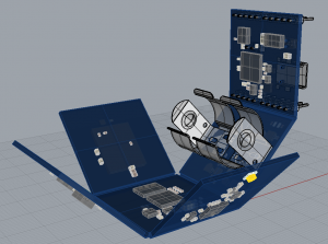
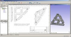
STEP Design Files or STP Design Files is a 3D CAD design file format used in the manufacturing production process. A STEP design file is a file extension for a 3-D graphic file used by CAD software. STEP stands for STandard for the Exchange of Product model data. STEP files are used to store 3D image data in an ASCII format, following the standards defined in ISO.

STEP File Design
STEP File Design

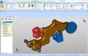
STEP Design is a 3d design format that is supported by most CAD software and engineering software such as Solidworks.
Also; STEP design files can be read by windows notepad and be read by programmable software such as Matlab. A STEP file is not editable and the design tree of the model is not available.

A STEP file is a neutral file format that allows the transfer of files between different CAD software. STEP is more recent than IGES and seems to be more reliable. 3D models can be produced from these files and used for analysis, modeling, renderings and manufacturing drawings.

STEP File Designs
STEP File Designs

A message from the 3D Printing Expert and Product Design Experts president/owner:

I’m here to assist inventors, companies and organizations with all their 3D CAD STEP File Design and Manufacturing Pricing. I will provide you with expert STEP file design service and solutions.
Thanks for taking the time to view this 3D CAD STEP File Design website.
I look forward to working with you,

Anthony
President/Owner

Contact Us Now at 3D Printing and Product STEP Design File Experts

Filed Under: 3D CAD - Product Design, Production and Manufacturing Molds - Manufacturing Design

October 31, 2015 by 3D Prototype Designer

What Is Product Design ?

Many manufacturers and 3d printers will request a STP, STEP or IGS, IGES or STL file product design drawings for designing molds or for pricing manufactured parts for production of your invention or product or to build a 3d print prototype.

What is  Product Design
Product Design

IGES or IGS Files (design file format used in the manufacturing production process) stands for Initial Graphics Exchange Specification and is a file format which defines a vendor neutral data format that allows the digital exchange of information among Computer-Aided Design (CAD) systems. An IGS file is composed of 80-character ASCII records, a record length derived from the original punched card era. It can be used by many CAD programs as a standard ASCII text-based format for saving and exporting vector data, and can store wireframe models, surface or solid object representations, circuit diagrams, and other objects. The IGS format has become the default standard file format for transferring 3D model files between the different CAD software packages. Once a user has created a model file in one specific software to send it to another user who does not have that same program without any concern whether or not the recipient will have the ability to open or view the file.

STEP or STP Files (design file format used in the manufacturing production process) is a file extension for a 3-D graphic file used by CAD software. STP stands for STandard for the Exchange of Product model data. STP files are used to store 3D image data in an ASCII format, following the standards defined in ISO 10303-21 : Clear Text Encoding of the Exchange Structure.

STL Files / Stereolithography – Standard Tessellation Language (design file format used in 3d printing product parts and prototypes) is a file format native to the stereolithography CAD software created by 3D Systems. STL is also known as Standard Tessellation Language. This file format is supported by many other software packages; it is widely used for rapid prototyping and computer-aided manufacturing (additive manufacturing or 3D printing). STL files describe only the surface geometry of a three dimensional object without any representation of color, texture or other common CAD model attributes. The STL format specifies both ASCII and binary representations. Binary files are more common, since they are more compact.

Please keep in mind that the product design file formats stated above are usually the most popular and will work for almost all product design requirements but there are exceptions. Always check with a product design professional in regards to your specific product design project.


A message from Anthony the president/owner:

I’m here to assist and service inventors, companies and organizations with all their Product Design and Prototype needs.

Filed Under: 3D CAD - Product Design

September 7, 2015 by 3D Prototype Designer

3D Design Modeling Thickness Guidelines for 3D Printing Models and Prototypes With Different Material

wall thickness for 3d printing material
Wall Thickness Design For 3D Printing Material
Before you decide to 3D print (and ideally before you start to design your model), you should know the basic guidelines for your printing material of choice.
PLEASE NOTE; when 3d designing using long protrusions with counterweight without any support at one end you will probably need additional thickness than the stated below minimums to support the counterweight.
3d printing wall thickness support
3D Printing Wall Thickness Support

ABS palstic
Minimum wall thickness 1 mm
Minimum details on a larger support 03 mm

AL or Alumide
Minimum wall thickness 1 mm
Minimum details on a larger support 0.4 – 0.5 mm

AG or Silver
Minimum wall thickness 0.5 mm
Minimum details on a larger support 0.3 mm

BS or Brass
Minimum wall thickness 0.5 mm
Minimum details on a larger support 0.3 mm

BZ or Bronze
Minimum wall thickness 0.5 mm
Minimum details on a larger support 0.3 mm

CE or Ceramics
Minimum wall thickness 5.0 mm
Minimum details on a larger support 2.0 mm

HS or High Detailed Stainless Steel
Minimum wall thickness 3.0 mm
Minimum details on a larger support 0.2 mm

MC or Multi Colored
Minimum wall thickness 2.0 mm
Minimum details on a larger support 0.8 mm

PA or Polyamide
Minimum wall thickness 1.0 mm
Minimum details on a larger support 0.3 mm

PG or Prime Gray
Minimum wall thickness 1.0 mm
Minimum details on a larger support 0.5 mm

RE or Printable Resin
Minimum wall thickness 1.0 mm
Minimum details on a larger support 0.3 mm

RL or Rubber Like
Minimum wall thickness 1.0 mm
Minimum details on a larger support 0.5 mm

ST or Steel
Minimum wall thickness 1.0 – 3.0 mm (depending on X, Y or Z dimensions)
Minimum details on a larger support 0.9 mm

WD or Wood
Minimum wall thickness 3.0 mm
Minimum details on a larger support 1.5 mm

3D Printing Design and Manufacturing Design guidelines are not always the same. If you do not have experience with designing for 3D printing, minimum wall thickness is an often encountered error. In the virtual world of rendering your model you may have any dimension or be as thick or thin as you want. However; if you would like to make a model in the real world using 3D printing keep in mind the minimum thickness rules. After you build your 3d printed prototype you can go back and change the thickness on your 3d design for the manufacturing process. And of course, depending on which manufacturing production process and material you choose you will need to have your design conform to the new rules of thickness and design for the manufacturing process, material and sometimes even the particular manufacturer.

Please keep in mind that the 3d printing wall thickness guidelines stated above are only general guidelines and your 3d print design may vary from within the stated guidelines to outside the stated guidelines. Always check with a professional in regards to your specific project.


A message from Anthony the president/owner:

I’m here to assist and service inventors, companies and organizations with all their 3D Printing.

Filed Under: 3D CAD - Product Design, 3D Printing Printer

September 7, 2015 by 3D Prototype Designer

Minimum Wall-Thickness for 3D Printing ?

wall thickness for 3d printing
Wall Thickness For 3D Printing Designs
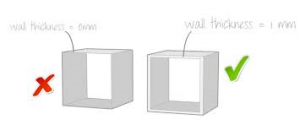
3D printing wall thickness may vary somewhat from 3d printer to 3d printer and another factor to be considered is material. Getting your model 3d printed just right will become much more complicated initially if the walls of the model are near or below the minimum wall thickness. You might inadvertently cause a hole in your 3d printed mesh (3d printed wall) for example. Or more commonly, make one part just a tad bit too thin which will cause it not to be 3D printed at all.

3d printing wall thickness support
3D Printing Wall Thickness Support With Counterweight Considerations To Support Extended Weight
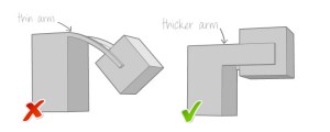
3D printing with ABS plastic is one of the more popular materials so we’ll use that material as our example 3d printing material. A wall thickness of at least 1mm minimum is a good rule thumb. Generally speaking I’d like to see closer to 2mm thickness when 3d printing especially when using minimum angle support 3d printer settings. However when using long protrusions with counterweight without any support at one end you will probably need to add thickness.

wall thickness for 3d printing design
3D Printing Wall Thickness

3D Printing Design and Manufacturing Design guidelines are not always the same. If you do not have experience with designing for 3D printing, minimum wall thickness is an often encountered error. In the virtual world of rendering your model you may have any dimension or be as thick or thin as you want. However; if you would like to make a model in the real world using 3D printing keep in mind the minimum thickness rules. After you build your 3d printed prototype you can go back and change the thickness on your 3d design for the manufacturing process. And of course, depending on which manufacturing production process and material you choose you will need to have your design conform to the new rules of thickness and design for the manufacturing process, material and sometimes even the particular manufacturer.

Before you decide to 3D print (and ideally before you start to design your model), you should know the basic guidelines for your printing material of choice. You can find specific information about the required wall thickness for each material in our 3d modeling design guide.
Please keep in mind that the 3d printing wall thickness guidelines stated above are only general guidelines and your 3d print design may vary from within the stated guidelines to outside the stated guidelines. Always check with a professional in regards to your specific project.


A message from Anthony the president/owner:

I’m here to assist and service inventors, companies and organizations with all their 3D Printing Service Requirements.

Filed Under: 3D CAD - Product Design, 3D Printing Printer

February 8, 2015 by 3D Prototype Designer

What is an OBJ File

OBJ File or .OBJ File is a geometry definition file format first developed by Wavefront Technologies for its Advanced Visualizer animation package. The file format is open and has been adopted by other 3D graphics application vendors.

A General Description of OBJ Files

Files that contain the .obj file extension hold 3D object files created with computer drawing software. These files can contain texture maps, 3D coordinates and other 3D object data.

The OBJ file format is used by a variety of 3D graphic applications. Some of the popular applications that use the .obj file extension include Microsoft Visual Studio and CADRazor.

The .obj file suffix is also used for computer science object files. These files contain a collection of sequences that hold instructions that tell a host machine how to accomplish a certain task. These OBJ files may be accompanied by related metadata files.

.obj files are also generated by several compilers on the Windows platform, e.g. C and C++ compilers. When a source code file is processed by the compiler, an .obj file is generated. When all source code files have been compiled to .obj files, the .obj files are linked together to the resulting .exe or .dll file.

OBJ File Format
OBJ File Format

A message from the president/owner:

I’m here to assist inventors, companies and organizations with all their 3D Printing and Prototyping needs and OBJ files. I will supply you with expert 3D Printing File and Fast Track Prototyping Files 3D Printing solutions.

Thanks for taking the time to view this .OBJ files web page.
I look forward to hearing from you,

Anthony
772-934-6014

Filed Under: 3D CAD - Product Design

  • 1
  • 2
  • Next Page »

Search This Website

3D Printing Expert Home Page – CLICK HERE

3D Printing-Prototype Pictures
Large 3D Printing & Prototypes

Phone 772-934-6014

rapid prototyping

Solve your 3D Printing Prototyping Needs Fast !

772-934-6014

Posts Categories

  • 3D CAD – Product Design (9)
  • 3D Printing Printer (26)
  • 3D Scanning (1)
  • Production and Manufacturing Molds – Manufacturing Design (6)
  • Prototype for Prototyping (9)
  • Prototyping / Product Development (17)

Most Recent Posts

  • What is a Radius or Corner Radii for Product Design
  • STEP Design Files is a 3D CAD design file format for manufacturing production
  • 3D Printing Allows Inventor to Bring His Unique Herb Grinder/Scale to Market – News Article
  • What is a 3D Printed Prototype and a Full Production Prototype?
  • 3D Printing and Prototypes with Photos – Pictures
  • 3D Scanning for Scans of Objects
  • Help Manufacturing Your Product or Invention
  • What is 3D Printing and 3D Prototypes
  • What Is Product Design ?
  • 3D Design Modeling Thickness Guidelines for 3D Printing Models and Prototypes With Different Material
  • Minimum Wall-Thickness for 3D Printing ?
  • CAD Design – IGES & STEP Manufacture Product Design
  • What Is A Functional Prototype
  • What Is A Visual Prototype
  • User Experience Prototype

Copyright 2019, Product Development Experts, Inc. This website built with - Product Development-WordPress website installation, design and marketing by SEO Wordpress Expert