3D Printing, 3D CAD Design and Rapid Prototyping
  • Home
  • Prototypes
    • Rapid Prototyping
    • Prototype Photos
  • CAD-Design
    • CAD Design
    • Manufacture Design STEP-IGES
    • Product Design
    • CAD – Prototypes
    • CAM
  • 3D Printing
    • 3D Printing Advantage
    • Large 3D Printing
    • 3D Printing Pictures
    • Types of 3D Printing
  • Examples
  • Scans
    • 3D Laser Scanning
    • 3D Scanning
  • Product Development
    • Manufacturing Pricing
    • Product Development
  • Contact Us
    • Make a Payment
    • Contact Us
  • Blog

October 1, 2019 by 3D Prototype Designer

What is a Radius or Corner Radii for Product Design

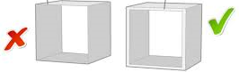
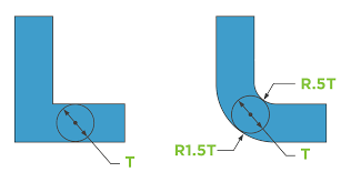
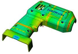
A Corner Radius or Corner Radii is a technical design term for simply rounding out or making smooth any sharp corner on a design. There are two types of radius: internal for inside corners and external for outside corners. Rather than leaving these corners sharp, a radius equal to at least 0.5 times the adjacent wall thickness is usually used.

A Fillet Radius or Fillet Radii is a rounding of an inside corner and are designed into molds to increase their load bearing strength and to improve both the plastic injection molding process and quality of the plastic part. For those reasons a fillet radius should be a standard allowance on every casting design. A “fillet radii” or “fillet radius” are commonly found on the bottom of a compartment or an inside corner and can be used in between bosses, ribs and gussets to connect them to a wall for added strength.

A Round Radius or Round Radii is a rounding of an outside corner of a part design and are designed into molds to increase their load bearing strength and to improve both the plastic injection molding process and quality of the plastic part. Sometimes a “chamfer” can be used to create a radius type design.

Radius Corners
ON LEFT: Without Using Radius / ON RIGHT Using Radius

Why use a design radius?

A radius is usually used for two reasons:

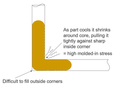
  1. To smooth out sharp corners on a design to make the design safer and more comfortable for handling.
  2. Rounding of sharp corners for plastic injection molding purposes so the outside corners of the part can fully fill and also helps prevent cracking of the inside corners of the part.
Radius Design for Plastic Injection Molds
When sharp corners are used in a mold the outside corners are hard to fill with plastic and then inside corners after injection will want to expand and crack.

Injection molding is a manufacturing process in which solid thermoplastic pellets are melted and injected into a mold. After this hot melt and fill process is completed the newly formed part is cooled back to a solid. During both, the injection and cooling stages, of the manufacturing process there are several design factors that may affect the quality of the final product and the consistent repeatability of the plastic injection manufacturing process.

When it comes to Manufacturing with Radius and Drafts it always best to have your manufacturer check your design to make sure it matches their manufacturing equipment tolerances and perform any design changes that may be required to achieve the highest manufacturing quality and cost advantages. Manufacturing equipment and materials will dictate the best mold design for your product parts.

radius bosses, ribs and gussets
Bosses, Ribs and Gussets Are Pictured Above

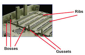
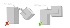
Sharp corners at the base of bosses, ribs and gussets should have Radius Design to help offset stress points. The edge where a boss meets a wall should have a radius used to reduce the sharp corner without increasing the wall thickness to much that it creates a sink problem.

radius design for product design molds
When the design is complete notice the rounded radius on all the corners on the outside of this drill cover case.

A message from the 3D Printing Expert and Product Design Experts president/owner:

I’m here to assist inventors, companies and organizations with all their 3D CAD Design Radius and Manufacturing Pricing. I will provide you with expert design radius service and solutions.
Thanks for taking the time to view this 3D CAD Radius Design website.
I look forward to working with you on your radius design goals, Anthony, President/Owner

Contact Us Now at 3D Printing and Product Radius Design File Experts

Filed Under: 3D Printing Printer, Production and Manufacturing Molds - Manufacturing Design

April 15, 2017 by 3D Prototype Designer

3D Printing Allows Inventor to Bring His Unique Herb Grinder/Scale to Market – News Article

Written by Whitney Hipolite for 3DPrint Online Magazine – The Voice of 3D Printing / Additive Manufacturing
(this is a partial repost from the original news article)

3d printing testing the prototype the grale
3D Printed Prototype of the Grale

For one young man, from Jupiter, Florida, named Josh Camitta, this wasn’t the case, simply because he discovered that 3D printing could provide him with answers that previous generations simply could not come up with.

“The product I have created is called The Grale; The first ever handheld vegetative (herbal) processor and weighing unit,” Camitta tells 3DPrint.com. “Once awarded the patent for this grinder/scale apparatus, I became highly motivated to take this project to the next level.”

Camitta’s apparatus could certainly be quite the useful device for chefs, cooks, and food vendors alike. It was just getting this product to market that was the challenging part. It all started with the desire and need to create a working prototype, and that’s when Anthony Dichiara of 3D-Printing-Expert.com came to the aid.

a 3d printed prototype of the grale
The 3D Printed Grale Ready for Product Testing

The Grale features an optimized grinding process with two sets of aluminum CNC milled teeth. A user is required to choose their desired herb or vegetative material. It is then placed into the device, where it is ground before falling through to the next chamber. Food such as herbs, coffee, spice, etc. may be used in raw form. When the material/food falls into the chamber, it is simultaneously weighed.

“For this weighing process the material is collected on what we call the reservoir tray,” explained Camitta. “From here the user has many options. One option is to simply unscrew the top and pinch out the desired portion. Alternatively, you could opt to use the small door (EZ-Pour Technology) which allows the operator to simply swing open a magnetized door, enabling the material to pour out, like a tea kettle. Additionally, one can simply open the larger door and remove the entire reservoir tray for easy access and control.”

Camitta originally was prototyping his design using stereolithography 3D printing technology, but found that it was really quite expensive, inefficient, and restrictive for his purposes. So when he found Dichiara with the 3D Printing and Product Design Company, he was greatly relieved. Dichiara was able to print out a whole swath of parts quickly and inexpensively, allowing Camitta to better understand how his device would function and fit together.
“The combination of a strong engineer (Anthony DiChiara) and the technology of a his 3-D printing process, made making small adaptations and changes a fluid part of the prototype process,” says Camitta. “This has enabled my project to continue to progress with both confidence and pace as it moves towards completion.”

3d printing of a 3d printed working prototype
The Grale Working Prototype Different Working Parts

This is just one more shining example of how 3D printing is allowing the innovators of the world test the feasibility of their inventions using a really tangible means of production.

For the full article go to 3DPrint “The Voice of 3D Printing / Additive Manufacturing”


prototype product development
What was once just an idea is now a finished new consumer product ready for sale by the inventor, Josh Camitta of Jupiter Florida, who used our “3D Printing – Prototype Design and Product Development Program”

Filed Under: 3D Printing Printer

January 24, 2016 by 3D Prototype Designer

What is 3D Printing and 3D Prototypes

3D printing is also known as 3d rapid prototyping. It is a prototyping process whereby an real object is created from a 3D CAD design. The digital 3D CAD model design is saved in STL file format and then sent to a 3D printer. The 3D printer will then have the three dimensional instructions to print the design layer by layer and form a real object on a flat build bed.
What is 3D printing
“3D Printing has emerged as the most valuable new tool for inventors looking for prototypes”.

“3D printing is positively impacting many industries, such as automotive, medical, business & industrial equipment, education, architecture, and consumer-product industries”.

For creating a three D printed object you need a digital 3D CAD design model. The digital 3D-model is usually saved in STL format and then sent to the printer.

3D Printed Prototype

3D printing can provide great savings on assembly costs because it can print already assembled products. With 3D printing, companies can now experiment with new ideas and numerous test design with no extensive time or tooling expense. They can decide if product concepts are worth funding.


A message from Anthony the president/owner:

I’m here to assist and service inventors, companies and organizations with all their 3D printing service needs.

Filed Under: 3D Printing Printer

September 7, 2015 by 3D Prototype Designer

3D Design Modeling Thickness Guidelines for 3D Printing Models and Prototypes With Different Material

wall thickness for 3d printing material
Wall Thickness Design For 3D Printing Material
Before you decide to 3D print (and ideally before you start to design your model), you should know the basic guidelines for your printing material of choice.
PLEASE NOTE; when 3d designing using long protrusions with counterweight without any support at one end you will probably need additional thickness than the stated below minimums to support the counterweight.
3d printing wall thickness support
3D Printing Wall Thickness Support

ABS palstic
Minimum wall thickness 1 mm
Minimum details on a larger support 03 mm

AL or Alumide
Minimum wall thickness 1 mm
Minimum details on a larger support 0.4 – 0.5 mm

AG or Silver
Minimum wall thickness 0.5 mm
Minimum details on a larger support 0.3 mm

BS or Brass
Minimum wall thickness 0.5 mm
Minimum details on a larger support 0.3 mm

BZ or Bronze
Minimum wall thickness 0.5 mm
Minimum details on a larger support 0.3 mm

CE or Ceramics
Minimum wall thickness 5.0 mm
Minimum details on a larger support 2.0 mm

HS or High Detailed Stainless Steel
Minimum wall thickness 3.0 mm
Minimum details on a larger support 0.2 mm

MC or Multi Colored
Minimum wall thickness 2.0 mm
Minimum details on a larger support 0.8 mm

PA or Polyamide
Minimum wall thickness 1.0 mm
Minimum details on a larger support 0.3 mm

PG or Prime Gray
Minimum wall thickness 1.0 mm
Minimum details on a larger support 0.5 mm

RE or Printable Resin
Minimum wall thickness 1.0 mm
Minimum details on a larger support 0.3 mm

RL or Rubber Like
Minimum wall thickness 1.0 mm
Minimum details on a larger support 0.5 mm

ST or Steel
Minimum wall thickness 1.0 – 3.0 mm (depending on X, Y or Z dimensions)
Minimum details on a larger support 0.9 mm

WD or Wood
Minimum wall thickness 3.0 mm
Minimum details on a larger support 1.5 mm

3D Printing Design and Manufacturing Design guidelines are not always the same. If you do not have experience with designing for 3D printing, minimum wall thickness is an often encountered error. In the virtual world of rendering your model you may have any dimension or be as thick or thin as you want. However; if you would like to make a model in the real world using 3D printing keep in mind the minimum thickness rules. After you build your 3d printed prototype you can go back and change the thickness on your 3d design for the manufacturing process. And of course, depending on which manufacturing production process and material you choose you will need to have your design conform to the new rules of thickness and design for the manufacturing process, material and sometimes even the particular manufacturer.

Please keep in mind that the 3d printing wall thickness guidelines stated above are only general guidelines and your 3d print design may vary from within the stated guidelines to outside the stated guidelines. Always check with a professional in regards to your specific project.


A message from Anthony the president/owner:

I’m here to assist and service inventors, companies and organizations with all their 3D Printing.

Filed Under: 3D CAD - Product Design, 3D Printing Printer

September 7, 2015 by 3D Prototype Designer

Minimum Wall-Thickness for 3D Printing ?

wall thickness for 3d printing
Wall Thickness For 3D Printing Designs
3D printing wall thickness may vary somewhat from 3d printer to 3d printer and another factor to be considered is material. Getting your model 3d printed just right will become much more complicated initially if the walls of the model are near or below the minimum wall thickness. You might inadvertently cause a hole in your 3d printed mesh (3d printed wall) for example. Or more commonly, make one part just a tad bit too thin which will cause it not to be 3D printed at all.

3d printing wall thickness support
3D Printing Wall Thickness Support With Counterweight Considerations To Support Extended Weight
3D printing with ABS plastic is one of the more popular materials so we’ll use that material as our example 3d printing material. A wall thickness of at least 1mm minimum is a good rule thumb. Generally speaking I’d like to see closer to 2mm thickness when 3d printing especially when using minimum angle support 3d printer settings. However when using long protrusions with counterweight without any support at one end you will probably need to add thickness.

wall thickness for 3d printing design
3D Printing Wall Thickness

3D Printing Design and Manufacturing Design guidelines are not always the same. If you do not have experience with designing for 3D printing, minimum wall thickness is an often encountered error. In the virtual world of rendering your model you may have any dimension or be as thick or thin as you want. However; if you would like to make a model in the real world using 3D printing keep in mind the minimum thickness rules. After you build your 3d printed prototype you can go back and change the thickness on your 3d design for the manufacturing process. And of course, depending on which manufacturing production process and material you choose you will need to have your design conform to the new rules of thickness and design for the manufacturing process, material and sometimes even the particular manufacturer.

Before you decide to 3D print (and ideally before you start to design your model), you should know the basic guidelines for your printing material of choice. You can find specific information about the required wall thickness for each material in our 3d modeling design guide.
Please keep in mind that the 3d printing wall thickness guidelines stated above are only general guidelines and your 3d print design may vary from within the stated guidelines to outside the stated guidelines. Always check with a professional in regards to your specific project.


A message from Anthony the president/owner:

I’m here to assist and service inventors, companies and organizations with all their 3D Printing Service Requirements.

Filed Under: 3D CAD - Product Design, 3D Printing Printer

  • 1
  • 2
  • 3
  • …
  • 6
  • Next Page »

Search This Website

3D Printing Expert Home Page – CLICK HERE

3D Printing-Prototype Pictures
Large 3D Printing & Prototypes

Phone 772-934-6014

rapid prototyping

Solve your 3D Printing Prototyping Needs Fast !

772-934-6014

Posts Categories

  • 3D CAD – Product Design (10)
  • 3D Printing Printer (26)
  • 3D Scanning (1)
  • Production and Manufacturing Molds – Manufacturing Design (8)
  • Prototype for Prototyping (9)
  • Prototyping / Product Development (17)

Most Recent Posts

  • What is a Draft Angle or Draft for Plastic Injection Molding Design
  • What is a Radius or Corner Radii for Product Design
  • STEP Design Files is a 3D CAD design file format for manufacturing production
  • 3D Printing Allows Inventor to Bring His Unique Herb Grinder/Scale to Market – News Article
  • What is a 3D Printed Prototype and a Full Production Prototype?
  • 3D Printing and Prototypes with Photos – Pictures
  • 3D Scanning for Scans of Objects
  • Help Manufacturing Your Product or Invention
  • What is 3D Printing and 3D Prototypes
  • What Is Product Design ?
  • 3D Design Modeling Thickness Guidelines for 3D Printing Models and Prototypes With Different Material
  • Minimum Wall-Thickness for 3D Printing ?
  • CAD Design – IGES & STEP Manufacture Product Design
  • What Is A Functional Prototype
  • What Is A Visual Prototype

Copyright 2013 -2022, 3D-Printing-Expert.com by Product Development Experts, Inc. This website built with Product Development website installation, design and marketing by SEO Website Design