3D Printing, 3D CAD Design and Rapid Prototyping
  • Home
  • Prototypes
    • Rapid Prototyping
    • Prototype Photos
  • CAD-Design
    • CAD Design
    • Manufacture Design STEP-IGES
    • Product Design
    • CAD – Prototypes
    • CAM
  • 3D Printing
    • 3D Printing Advantage
    • Large 3D Printing
    • 3D Printing Pictures
    • Types of 3D Printing
  • Examples
  • Scans
    • 3D Laser Scanning
    • 3D Scanning
  • Product Development
    • Manufacturing Pricing
    • Product Development
  • Contact Us
    • Make a Payment
    • Contact Us
  • Blog

April 4, 2021 by 3D Prototype Designer

What is a Draft Angle or Draft for Plastic Injection Molding Design

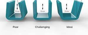
A Draft Angle or Draft for Plastic Injection Molding Design is a technical design term for simply adding a draft angle of 1½ to 2 degrees on a product design for a mold that is used in product manufacturing

what is a draft angle
What is the Ideal Draft Angle for Manufacturing with Plastic Injection Molding

The advantages of using a design draft angle for plastic injection molded parts:

Helps to reduce the chance of damage to the part due to friction while part is being released from the mold.
Helps promote less wear and tear and less hands on physical removal of part the from the mold.
Helps to maintain a uniform, smooth, unscratched finish where desired.
Helps maintain the integrity and uniformity of textured or non-smooth designed surfaces.
Helps to eliminate the need for unconventional ejection of the part from the mold.

The above draft angle design advantages in most plastic injection situations will lower production cost.

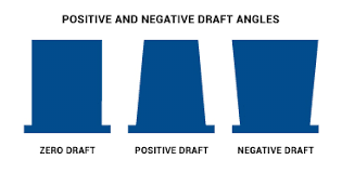
Positive Draft vs Negative Draft

Positive draft: A positive draft means the angle of the face, with respect to the direction of pull, is more than the reference angle. A positive draft is the amount of taper for molded or cast parts perpendicular to the parting line allowing for a single mold.

Negative draft: A negative draft means the angle of the face, with respect to the direction of the pull, is less than the negative reference angle. The manufacture of a part that incorporates zero or negative angles may require a mold that can be separated into two or more parts in order to release the casting.

Zero Draft Design vs Positive Draft Design vs Negative Draft Design
What is Zero Draft Design vs Positive Draft Design vs Negative Draft Design

Plastic injection molding is a manufacturing process in which solid thermoplastic pellets are melted and injected into a mold. After this hot melt and fill process is completed the newly formed part is cooled back to a solid. During both, the injection and cooling stages, of the manufacturing process there are several design factors that may affect the quality of the final product and the consistent repeatability of the plastic injection manufacturing process.

When it comes to Manufacturing with Drafts and Radius it always best to have your manufacturer check your design to make sure it matches their manufacturing equipment tolerances and perform any design changes that may be required to achieve the highest manufacturing quality and cost advantages. Manufacturing equipment and materials will dictate the best mold design for your product parts.

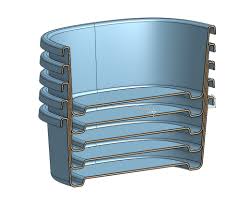
Draft Angles are also used to make products or parts for stacking within each other. Stacking parts can save space on store shelf pace and warehouse storage and shipping storage containers which helps reduce the storage cost of your product. The handling cost of multiple units at one time is also reduced. Stacking your products within each other helps to reduce your overall product cost.

draft angle for stacking product for shipping and storage and handling savings
Draft Angle for Stacking Product for Shipping, Storage and Handling

A message from the 3D Printing Expert and Product Design Experts president/owner:

I’m here to assist inventors, companies and organizations with all their 3D CAD design draft angle and manufacturing questions and requirements. I will provide you with expert draft angle design service and solutions.
Thanks for taking the time to view this Draft Angle Design website.
I look forward to working with you on your draft design goals, Anthony, President/Owner

Contact Us Now at 3D Printing and Product Draft Angle Design Experts

Filed Under: 3D CAD - Product Design, Production and Manufacturing Molds - Manufacturing Design

October 1, 2019 by 3D Prototype Designer

What is a Radius or Corner Radii for Product Design

A Corner Radius or Corner Radii is a technical design term for simply rounding out or making smooth any sharp corner on a design. There are two types of radius: internal for inside corners and external for outside corners. Rather than leaving these corners sharp, a radius equal to at least 0.5 times the adjacent wall thickness is usually used.

A Fillet Radius or Fillet Radii is a rounding of an inside corner and are designed into molds to increase their load bearing strength and to improve both the plastic injection molding process and quality of the plastic part. For those reasons a fillet radius should be a standard allowance on every casting design. A “fillet radii” or “fillet radius” are commonly found on the bottom of a compartment or an inside corner and can be used in between bosses, ribs and gussets to connect them to a wall for added strength.

A Round Radius or Round Radii is a rounding of an outside corner of a part design and are designed into molds to increase their load bearing strength and to improve both the plastic injection molding process and quality of the plastic part. Sometimes a “chamfer” can be used to create a radius type design.

Radius Corners
ON LEFT: Without Using Radius / ON RIGHT Using Radius

Why use a design radius?

A radius is usually used for two reasons:

  1. To smooth out sharp corners on a design to make the design safer and more comfortable for handling.
  2. Rounding of sharp corners for plastic injection molding purposes so the outside corners of the part can fully fill and also helps prevent cracking of the inside corners of the part.
Radius Design for Plastic Injection Molds
When sharp corners are used in a mold the outside corners are hard to fill with plastic and then inside corners after injection will want to expand and crack.

Injection molding is a manufacturing process in which solid thermoplastic pellets are melted and injected into a mold. After this hot melt and fill process is completed the newly formed part is cooled back to a solid. During both, the injection and cooling stages, of the manufacturing process there are several design factors that may affect the quality of the final product and the consistent repeatability of the plastic injection manufacturing process.

When it comes to Manufacturing with Radius and Drafts it always best to have your manufacturer check your design to make sure it matches their manufacturing equipment tolerances and perform any design changes that may be required to achieve the highest manufacturing quality and cost advantages. Manufacturing equipment and materials will dictate the best mold design for your product parts.

radius bosses, ribs and gussets
Bosses, Ribs and Gussets Are Pictured Above

Sharp corners at the base of bosses, ribs and gussets should have Radius Design to help offset stress points. The edge where a boss meets a wall should have a radius used to reduce the sharp corner without increasing the wall thickness to much that it creates a sink problem.

radius design for product design molds
When the design is complete notice the rounded radius on all the corners on the outside of this drill cover case.

A message from the 3D Printing Expert and Product Design Experts president/owner:

I’m here to assist inventors, companies and organizations with all their 3D CAD Design Radius and Manufacturing Pricing. I will provide you with expert design radius service and solutions.
Thanks for taking the time to view this 3D CAD Radius Design website.
I look forward to working with you on your radius design goals, Anthony, President/Owner

Contact Us Now at 3D Printing and Product Radius Design File Experts

Filed Under: 3D Printing Printer, Production and Manufacturing Molds - Manufacturing Design

October 1, 2018 by 3D Prototype Designer

STEP Design Files is a 3D CAD design file format for manufacturing production

STEP Design Files or STP Design Files is a 3D CAD design file format used in the manufacturing production process. A STEP design file is a file extension for a 3-D graphic file used by CAD software. STEP stands for STandard for the Exchange of Product model data. STEP files are used to store 3D image data in an ASCII format, following the standards defined in ISO.

STEP File Design
STEP File Design

STEP Design is a 3d design format that is supported by most CAD software and engineering software such as Solidworks.
Also; STEP design files can be read by windows notepad and be read by programmable software such as Matlab. A STEP file is not editable and the design tree of the model is not available.

A STEP file is a neutral file format that allows the transfer of files between different CAD software. STEP is more recent than IGES and seems to be more reliable. 3D models can be produced from these files and used for analysis, modeling, renderings and manufacturing drawings.

STEP File Designs
STEP File Designs

A message from the 3D Printing Expert and Product Design Experts president/owner:

I’m here to assist inventors, companies and organizations with all their 3D CAD STEP File Design and Manufacturing Pricing. I will provide you with expert STEP file design service and solutions.
Thanks for taking the time to view this 3D CAD STEP File Design website.
I look forward to working with you,

Anthony
President/Owner

Contact Us Now at 3D Printing and Product STEP Design File Experts

Filed Under: 3D CAD - Product Design, Production and Manufacturing Molds - Manufacturing Design

April 15, 2017 by 3D Prototype Designer

3D Printing Allows Inventor to Bring His Unique Herb Grinder/Scale to Market – News Article

Written by Whitney Hipolite for 3DPrint Online Magazine – The Voice of 3D Printing / Additive Manufacturing
(this is a partial repost from the original news article)

3d printing testing the prototype the grale
3D Printed Prototype of the Grale

For one young man, from Jupiter, Florida, named Josh Camitta, this wasn’t the case, simply because he discovered that 3D printing could provide him with answers that previous generations simply could not come up with.

“The product I have created is called The Grale; The first ever handheld vegetative (herbal) processor and weighing unit,” Camitta tells 3DPrint.com. “Once awarded the patent for this grinder/scale apparatus, I became highly motivated to take this project to the next level.”

Camitta’s apparatus could certainly be quite the useful device for chefs, cooks, and food vendors alike. It was just getting this product to market that was the challenging part. It all started with the desire and need to create a working prototype, and that’s when Anthony Dichiara of 3D-Printing-Expert.com came to the aid.

a 3d printed prototype of the grale
The 3D Printed Grale Ready for Product Testing

The Grale features an optimized grinding process with two sets of aluminum CNC milled teeth. A user is required to choose their desired herb or vegetative material. It is then placed into the device, where it is ground before falling through to the next chamber. Food such as herbs, coffee, spice, etc. may be used in raw form. When the material/food falls into the chamber, it is simultaneously weighed.

“For this weighing process the material is collected on what we call the reservoir tray,” explained Camitta. “From here the user has many options. One option is to simply unscrew the top and pinch out the desired portion. Alternatively, you could opt to use the small door (EZ-Pour Technology) which allows the operator to simply swing open a magnetized door, enabling the material to pour out, like a tea kettle. Additionally, one can simply open the larger door and remove the entire reservoir tray for easy access and control.”

Camitta originally was prototyping his design using stereolithography 3D printing technology, but found that it was really quite expensive, inefficient, and restrictive for his purposes. So when he found Dichiara with the 3D Printing and Product Design Company, he was greatly relieved. Dichiara was able to print out a whole swath of parts quickly and inexpensively, allowing Camitta to better understand how his device would function and fit together.
“The combination of a strong engineer (Anthony DiChiara) and the technology of a his 3-D printing process, made making small adaptations and changes a fluid part of the prototype process,” says Camitta. “This has enabled my project to continue to progress with both confidence and pace as it moves towards completion.”

3d printing of a 3d printed working prototype
The Grale Working Prototype Different Working Parts

This is just one more shining example of how 3D printing is allowing the innovators of the world test the feasibility of their inventions using a really tangible means of production.

For the full article go to 3DPrint “The Voice of 3D Printing / Additive Manufacturing”


prototype product development
What was once just an idea is now a finished new consumer product ready for sale by the inventor, Josh Camitta of Jupiter Florida, who used our “3D Printing – Prototype Design and Product Development Program”

Filed Under: 3D Printing Printer

February 17, 2017 by 3D Prototype Designer

What is a 3D Printed Prototype and a Full Production Prototype?

Technically speaking a “3D Printed Prototype” and a “Full Production Prototype” are both 3D (three dimensional) prototypes.

1) 3D printed prototype are a lower cost and are a quicker to build prototype which usually helps prove the design, concept and size and feel. This is a type of prototype that is used during the design and engineering process and before you enter the expensive manufacturing process. THREE D PRINTED PROTOTYPES ARE USED BEFORE THE MANUFACTURE PROCESS

2) Full production prototype are constructed from the same materials (or close to ) the finished manufactured product and sometimes uses the production molds. A FULL PRODUCTION PROTOTYPE IS USUALLY USED AFTER THE PRODUCT DESIGN AND ENGINEERING IS COMPLETED OR AT THE BEGINNING OF THE MANUFACTURING PROCESS

Depending on what your product or invention is it may not be necessary to build both types of prototypes.

3D Printed Prototypes and Full Production Prototypes pictures

3d printed prototype product model
3D Printed Prototype Product Model

full production working prototype
Full Production Working Prototype

3D Printing Large Prototype
3D Printed Large Prototype for “Rippleball” Swimming Pool Game

Click Here to View More 3D Printed Photos and Pictures

A message from the 3D Printing, Product Design & Prototype Experts president/owner:

Don’t underestimate the importance of a prototype and don’t try to cut corners by skipping the prototype stage and moving forward without having proven to yourself and others that your idea is technically and mechanically feasible.

What are the Different Types of Prototypes

I’m here to provide 3d printing prototype services to inventors, companies and organizations interested in having their product or item prototyped for reproduction or product design modifications, alterations or design improvements. I will supply you with expert 3d printing and prototyping service solutions.

Thanks for taking the time to view this 3d printing and prototype company information and I look forward to hearing from you,
Anthony, President and Chief Prototype and Product Designer
3D Printing Expert, Inc.
772-934-6014

Filed Under: Prototype for Prototyping, Prototyping / Product Development

  • 1
  • 2
  • 3
  • …
  • 10
  • Next Page »

Search This Website

3D Printing Expert Home Page – CLICK HERE

3D Printing-Prototype Pictures
Large 3D Printing & Prototypes

Phone 772-934-6014

rapid prototyping

Solve your 3D Printing Prototyping Needs Fast !

772-934-6014

Posts Categories

  • 3D CAD – Product Design (10)
  • 3D Printing Printer (26)
  • 3D Scanning (1)
  • Production and Manufacturing Molds – Manufacturing Design (8)
  • Prototype for Prototyping (9)
  • Prototyping / Product Development (17)

Most Recent Posts

  • What is a Draft Angle or Draft for Plastic Injection Molding Design
  • What is a Radius or Corner Radii for Product Design
  • STEP Design Files is a 3D CAD design file format for manufacturing production
  • 3D Printing Allows Inventor to Bring His Unique Herb Grinder/Scale to Market – News Article
  • What is a 3D Printed Prototype and a Full Production Prototype?
  • 3D Printing and Prototypes with Photos – Pictures
  • 3D Scanning for Scans of Objects
  • Help Manufacturing Your Product or Invention
  • What is 3D Printing and 3D Prototypes
  • What Is Product Design ?
  • 3D Design Modeling Thickness Guidelines for 3D Printing Models and Prototypes With Different Material
  • Minimum Wall-Thickness for 3D Printing ?
  • CAD Design – IGES & STEP Manufacture Product Design
  • What Is A Functional Prototype
  • What Is A Visual Prototype

Copyright 2013 -2022, 3D-Printing-Expert.com by Product Development Experts, Inc. This website built with Product Development website installation, design and marketing by SEO Website Design