PLEASE NOTE; when 3d designing using long protrusions with counterweight without any support at one end you will probably need additional thickness than the stated below minimums to support the counterweight.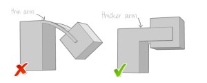
ABS palstic
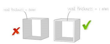
Minimum wall thickness 1 mm
Minimum details on a larger support 03 mm
AL or Alumide
Minimum wall thickness 1 mm
Minimum details on a larger support 0.4 – 0.5 mm
AG or Silver
Minimum wall thickness 0.5 mm
Minimum details on a larger support 0.3 mm
BS or Brass
Minimum wall thickness 0.5 mm
Minimum details on a larger support 0.3 mm
BZ or Bronze
Minimum wall thickness 0.5 mm
Minimum details on a larger support 0.3 mm
CE or Ceramics
Minimum wall thickness 5.0 mm
Minimum details on a larger support 2.0 mm
HS or High Detailed Stainless Steel
Minimum wall thickness 3.0 mm
Minimum details on a larger support 0.2 mm
MC or Multi Colored
Minimum wall thickness 2.0 mm
Minimum details on a larger support 0.8 mm
PA or Polyamide
Minimum wall thickness 1.0 mm
Minimum details on a larger support 0.3 mm
PG or Prime Gray
Minimum wall thickness 1.0 mm
Minimum details on a larger support 0.5 mm
RE or Printable Resin
Minimum wall thickness 1.0 mm
Minimum details on a larger support 0.3 mm
RL or Rubber Like
Minimum wall thickness 1.0 mm
Minimum details on a larger support 0.5 mm
ST or Steel
Minimum wall thickness 1.0 – 3.0 mm (depending on X, Y or Z dimensions)
Minimum details on a larger support 0.9 mm
WD or Wood
Minimum wall thickness 3.0 mm
Minimum details on a larger support 1.5 mm
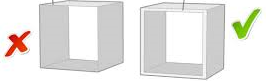
3D Printing Design and Manufacturing Design guidelines are not always the same. If you do not have experience with designing for 3D printing, minimum wall thickness is an often encountered error. In the virtual world of rendering your model you may have any dimension or be as thick or thin as you want. However; if you would like to make a model in the real world using 3D printing keep in mind the minimum thickness rules. After you build your 3d printed prototype you can go back and change the thickness on your 3d design for the manufacturing process. And of course, depending on which manufacturing production process and material you choose you will need to have your design conform to the new rules of thickness and design for the manufacturing process, material and sometimes even the particular manufacturer.
Please keep in mind that the 3d printing wall thickness guidelines stated above are only general guidelines and your 3d print design may vary from within the stated guidelines to outside the stated guidelines. Always check with a professional in regards to your specific project.
A message from Anthony the president/owner:
I’m here to assist and service inventors, companies and organizations with all their 3D Printing.